Logic Circuit Trainer CPE-EO2110
Location :Home > Product Introduction > Edu. - ElectricityㆍElectronics > Logic Circuit Trainer CPE-EO2110
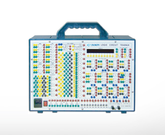
Logic Circuit Trainer
CPE-EO2110
CPE-EO2110
* Easy to practice as each gate sign and terminal was
positioned on the panel.
* Possible to build various circuits by connecting lead wires as
each gate has input/output terminal.
* Logic value is displayed "1" or "0" on FND display.
* Possible to make an application circuit practice as this unit has
rich elements.
* Loaded pulse generator and logic input switch.
Configuration/Specifications
1) 2 input and gate: 10ea
2) 4 input and gate: 10ea
3) 2 input or gate: 5ea
4) 4 input or gate: 2ea
5) 5 input or gate: 1ea
6) NOT gate: 6ea
7) 2 input Nand gate: 6ea
8) 2 input or gate: 2ea
9) 2 input ex-or gate: 2ea
10) R-S flip-flop: 2ea
11) J-K flip-flop: 4ea
12) 1 bit shift register: 4ea
13) LED "1", "0" indicator: 10ea
14) Level setting switch: 10ea
15) Clock: 10/1000Hz
16) One short pulse: 1ea
17) Manual pulse generator: 1ea
18) Front panel: FR-4(1.6t)
19) Rear panel: print circuit board
20) Dimension: 130(H) x 390(W) x 270(D)mm
21) Accessories
① User's manual: 1ea
② Power cord: 1ea
③ Test wire (0.8~1): 1 set
④ Spare fuse: 2ea
Experiment contents
1) AND circuit
2) OR circuit
3) NOR circuit
4) NAND circuit
5) NOR circuit
6) EXOR circuit
7) ADDER circuit
8) Encoder
9) Decoder
10) R/S flip-flop circuit
11) J/K flip-flop circuit
12) Asynchronous binary the 10th coefficient circuit by J/K flip-flop
13) Experiment of 4 bit serial input serial output shift registers that use NOT circuit.
14) Experiment of R-S flip-flop by NAND circuit and NOT circuit.
15) Experiment of pulse shaping circuit by NAND circuit and NOT circuit.
16) Experiment of unlimited multi-vibrator that use NOT circuit.
17) Experiment of asynchronous binary the third coefficient circuit.
18) Experiment of asynchronous binary the seventh coefficient circuit.
19) Experiment of asynchronous binary the ninth coefficient circuit.